

UC Davis Aeronautical Wind Tunnel (AWT) is used for both university affiliated research. The AWT is an open circuit tunnel with a 33.6″ x 48″ closed test section. A 125 horsepower motor produces a maximum velocity of 165 mph through the test section. Turbulence levels have been determined to be < 0.1% throughout the velocity range. A pyramidal balance measures all six force and moment components over a wide range of angle of attack and angle of yaw.
Contraction Section
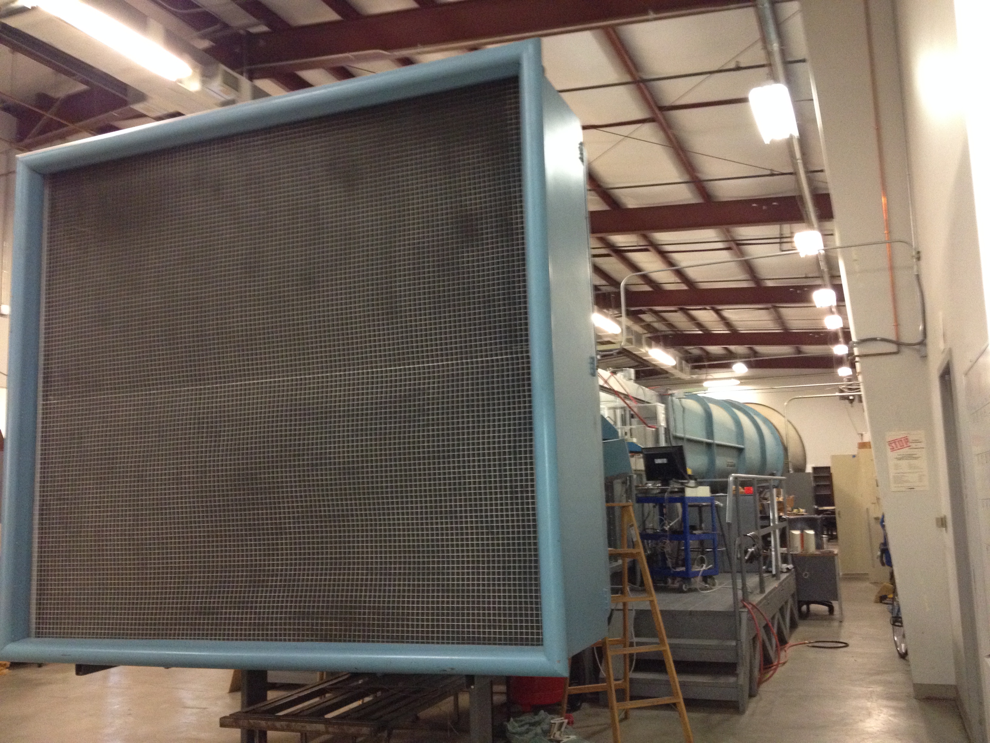
Contraction Section
Contraction ratio: 7.5:1
An aluminum honeycomb 6″ deep with .25″ cells (aspect ratio of 24) is located in the welded steel entrance chamber, protected by a coarse screen at the inlet. The honeycomb is followed by four 20 x 20 mesh (.009″ dia.) stainless steel anti-turbulence screens. Space is left for one additional screen.
The section is composed of four sides of identical curvature to provide equal pressures on adjoining sides at the corners to guard against the formation of corner vortices.
The coordinates of the contraction is derived from a ninth-order polynomial with three derivatives equated to zero at the entrance and five at the exit providing extremely gradual transition from and to axial flow.
Test Section

Test section, looking in direction of flow
Dimensions: 33.6″ x 48″ x 12′
Two 36″ turntables in the floor.
The test section is constructed with parallel sides instead of the usual practice of diverging two sides to allow for boundary layer growth. Four tapered fillets are installed in the test section to compensate for the narrowing of the flow channel due to boundary layer growth and to provide a constant static pressure throughout the test section.
Aluminum floor and ceiling. Side walls are clear plexiglass panels hinged at the top to provide four 64″ wide doors centered on each of the two turntables. The doors can be removed and replaced with special glass doors as necessary.
An 18″ ultraviolet light (F18T8-BLB) installed in one of the lower fillet panels can illuminate the upstream turntable for fluorescent visualization applications.
Illumination is provided by two 96″ fluorescent tubes (F96T8-SSCW) installed in the upper fillet panels.
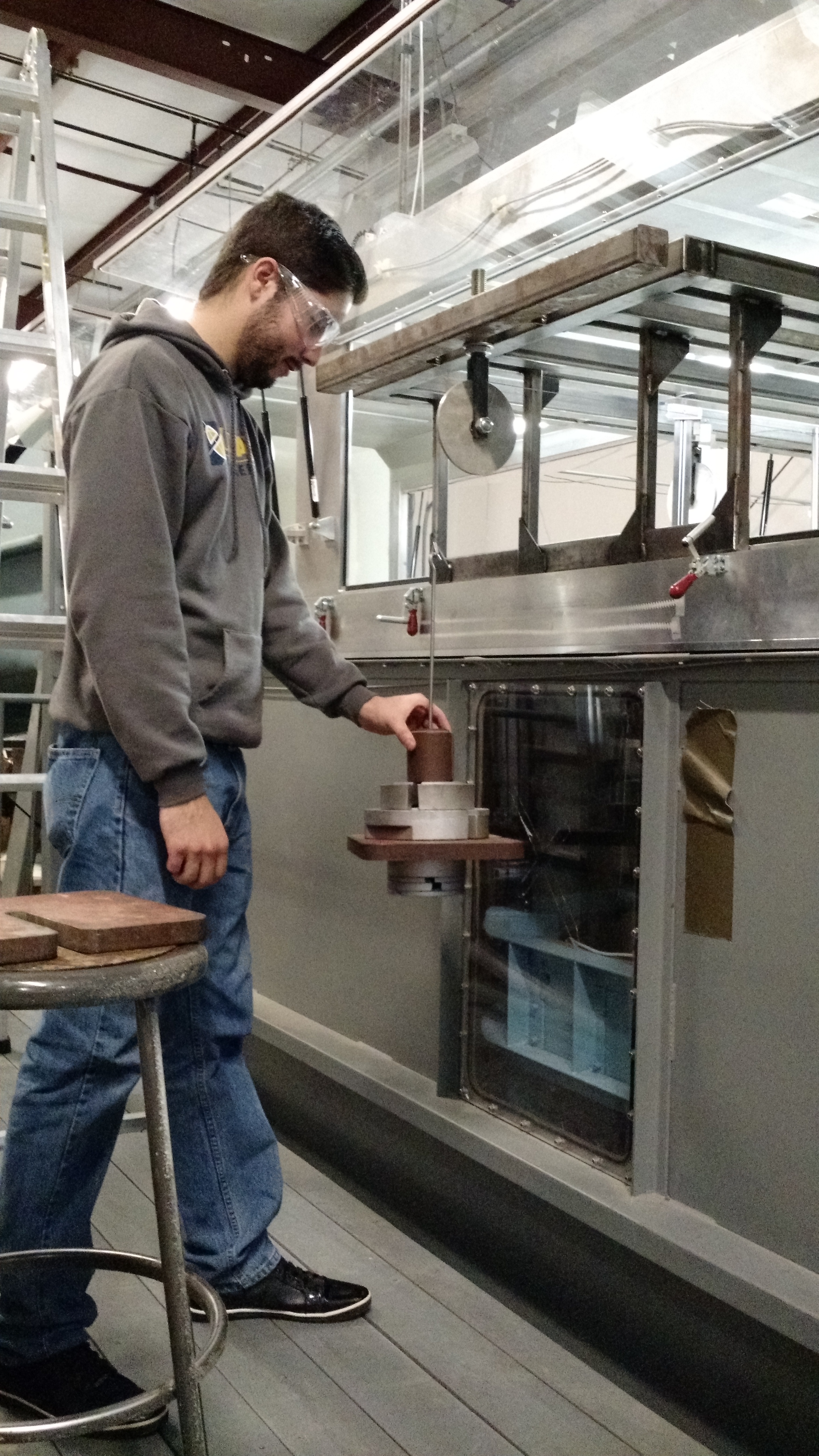
Balance, Measurement and Positioning Systems
Pyramidal balance system installed under the upstream turntable:
– Measures all six components of force and moment
– Positions model angle of yaw and angle of attack
– Calibrated as defined in the following document: calibration procedures
Pitot Static Calibration
Pyramidal Scale Calibration
Load and positioning limits:
| Lift | ±300 lb |
| Drag | ±50 lb |
| Side Force | ±150 lb |
| Pitching Moment | ± 70 ft-lb |
| Rolling Moment | ± 50 ft-lb |
| Yawing Moment | ± 50 ft-lb |
| Angle of Attack | ± 35 deg |
| Angle of Yaw | ± 45 deg |
Model positioning is performed by three Size 34 Slo-Syn stepper motors by the Superior Electric division of Warner Electric.
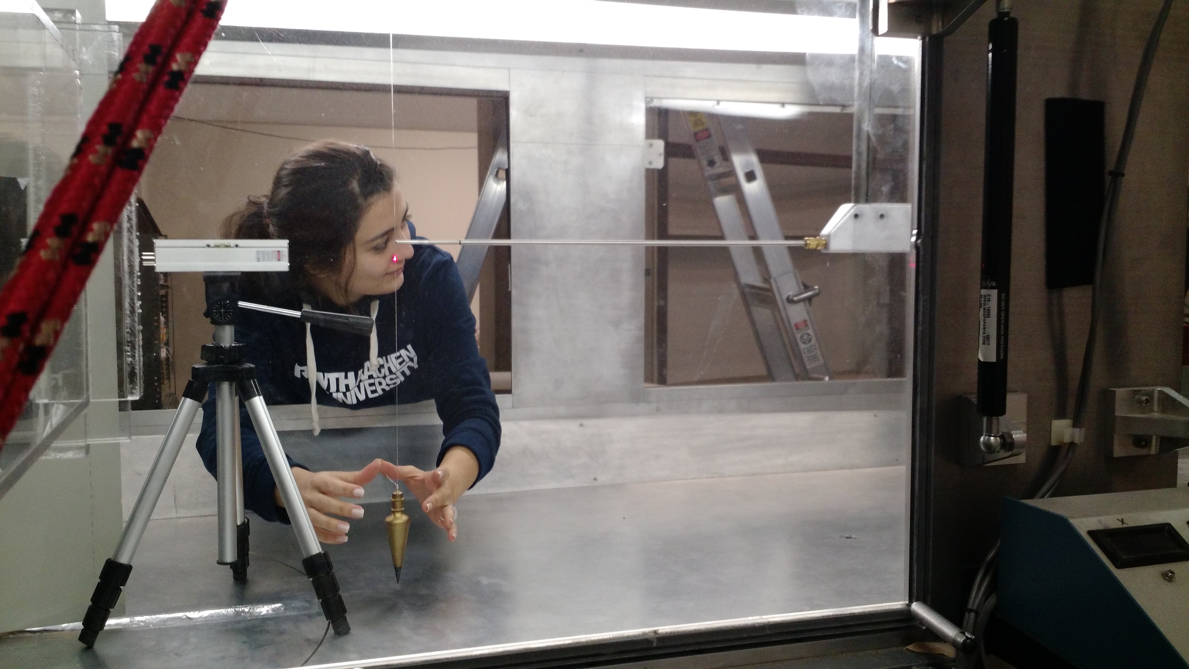
A two dimensional traversing mechanism installed from the ceiling of the test section is capable of moving a probe (e.g., hot wire, pitot tube) within a plane normal to the air flow. The traversing system can be manually placed at various longitudinal stations in the test section.
Diffuser, Power and Drive Systems
Fan: Joy size 84-26-FB-1000 Arrangement 4 direct drive Axivane vaneaxial fan
– Aluminum blades
– Blade pitch can be manually adjusted
Motor: Reliance Electric premium efficient motor
– Operates on 3 phase, 460 Volt, 60 Hz power
– Full load is approximately 138 amps at 1.0 service factor (125 hp) and 159 amps at 1.15 service factor (143 bhp)
Lubricant: Chevron SRI #2 or equivalent; additional information on nameplate mounted on side of fan
Speed Controller: Mitsubishi Meltrac A-100 variable frequency drive
– The drive is designated MT-A140E-110K-02UL and is designed for 216 amp variable torque.
– 1000:1 speed-ratio capability and can hold the fan speed constant with a maximum variation of ±0.2%.
A trash screen of 0.5″ mesh stainless steel is installed at the end of the diffuser to protect the fan.
Noise Suppression: Sound absorbing diffuser is installed downstream of the fan. The central fan is streamlined with a sound absorbent tail section supported by radial struts.
Central Positioning Control and Data Acquisition System
LabVIEW
Models
Airfoils
– Vertical span 12″ NACA 0012
– Vertical span 12″ S809
– Vertical span 12″ GU25–5(11)8
– Vertical span 18″ S819M with trailing edge slots for microtabs and microjet testing
3-D General Aviation Model
– Wing: 36″ span, 6″ chord, NACA 0012
– Ailerons: 8″ x 1.38″, coordinated or independent deflection
– Horizontal tail: 4″ chord, NACA 0012
– Elevator: 3.75″ x 2.12″
– Vertical tail with movable rudder
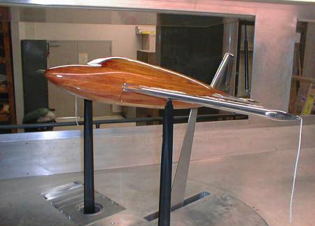
GA Model
Schematics
Side View
Top View
Front View